VT-120 GPS TRACKER FITTING INSTRUCTIONS WATERPROOF
ANTI THEFT TRACKER FITTING
WIRING DIAGRAM GPS TRACKER


How it works

Normally:

  • The relay connects pin 30 to 87a

  • The wire works as normal

  • The vehicle runs

When immobilised:

  • The relay disconnects 30 from 87a

  • Power to the fuel pump / ignition is cut

  • The engine stops


Immobilizer wiring

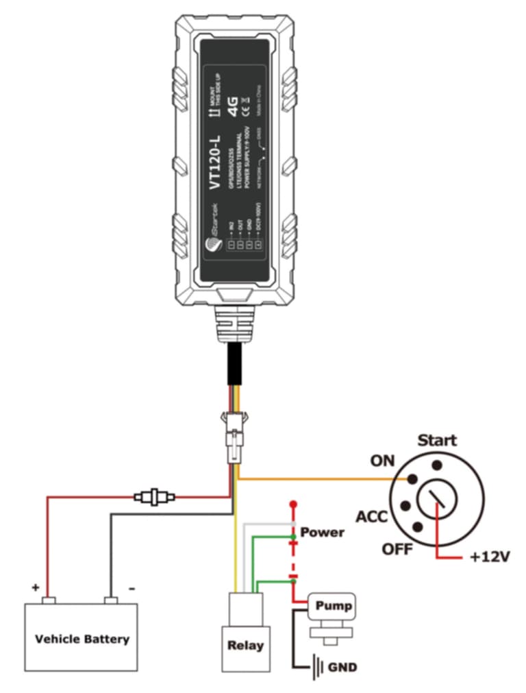
Basic Immobiliser Installation

  1. Install a 5-pin relay (30 / 85 / 86 / 87 / 87a).

  2. Locate the wire you want to interrupt
    This is usually the fuel pump power wire or ignition power wire.

  3. Cut this wire
    After cutting it you will have two loose ends.

  • One end goes towards the battery / fuse box

  • One end goes towards the fuel pump or ignition


Connect the relay

Pin 30 → one end of the cut wire

Pin 87a → the other end of the cut wire

(The relay simply sits in the middle of the wire you cut.)

Pin 85 → ignition switched +12V

Pin 86 → tracker immobiliser output wire           


Important

  • Only test immobilisation while the vehicle is stationary

  • Professional installation is recommended

REAL TIME LIVE PHONE GPS TRACKING APP
GPS TRACKER MOTORCYCLE BATTERY INSTALL
PLANT MACHINARY GPS TRACKER WATERPROOF

want more information?

Leave your details and we’ll give you a call.